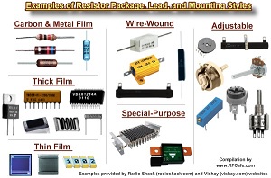
What is resistor?
Resistor
is a component that is used in electronic circuits and electrical networks to
primarily resist flow of current. It is
a passive component with two (or more) terminals and of variety of types as per
functions. The latest SMD resistors have
no leads but contact surfaces to connect electrically. According to Ohm’s law, in a DC circuit, (and
also in AC circuits, in case of pure resistance) the current through a resistor
is inversely proportional to its resistance, and directly proportional to the
voltage across it. Typical
applications and uses of resistors are: to reduce current flow, adjust signal
levels, to divide voltages, bias active elements, dissipate electrical power (as heat).
Resistor Value calculation, naming, colour codes and symbol

Resistors
are defined in terms of its resistance value in Ohms (or in Kilo-Ohms –
K). Also, rating of resistors is defined
in terms of watts. Resistor size changes
with variation in watts value for same value of resistance Wattage of resistors
varies from 1/8th W to few kW depending upon types). There are various ways of mentioning resistor
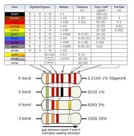
value and one way is by colour codes.
There are 3 or more colour bands with one band for tolerance and accordingly
value in terms of Ohms for any resistor can be defined. Details are in attached image.
Another
important factor associated with resistor value is its tolerance, i.e.
permissible variation in actual value.
Resistors with tolerance of 1% or less are used in precision electronic
circuits and these are depending upon their structure, like MFR or CERMET
resistors.
SMD
resistors have different methods of calculation of their values. Because of vary small size of SMD resistors,
they have a different system of coding. The most commonly seen codes are the
three- and four-digit system and an Electronic Industries Alliance (EIA) system
called EIA-96.
There
are resistors with zero (0) value also to be used in specific applications.
Types of resistors
Resistors are produced with a wide variety of
materials and manufacturing processes. Each resistor material has its typical
properties and specific areas of use. The main types that are used in
electrical engineering are summed below.
ü Wire wound (WW)
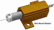
The wire wound resistor is
made by winding the metal wire around a metal core. In wire wound resistors,
metal wire is used as the resistance element and metal core is used as the
non-conductive material. Normally the
resistive wire is insulated, so that adjacent wires do not short together.
A Nichrome or
Manganin is commonly used as the metal wires, because they provide high
resistance to the electric current and operates at high temperature. Most
commonly used core materials include plastic, fiberglass, or ceramic.
Wire wound resistors were one of the
first types of resistor to be manufactured in the earliest days of electrical
science and then wireless. They were superseded in many applications by carbon
resistors and then metal oxide and metal film resistors. However, today, wire
would resistors are still used as the resistor of choice in many applications.
ü Carbon Composition (CCR)
Carbon composition resistors (CCR) consist of a solid
cylindrical resistive element with embedded wire leads or metal end caps to
which the lead wires are attached. The body of the resistor is protected with
paint or plastic. These resistors are the most commonly
used resistors in the 1960’s and earlier. However, now-a-days, carbon
composition resistors are rarely used because of its high cost and low
stability. The carbon composition resistors are also called carbon composition
or carbon resistors.
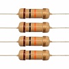
ü Carbon Film (CFR)
Carbon film
resistors are a significant improvement on carbon composition. However, in
comparison to metal film and metal oxide film, the commercially available range
steadily decreases. Metal and oxide film are not more expensive to produce, and
have overall better properties. Carbon
film resistors are a fixed form type resistor. They are constructed out of a
ceramic carrier with a thin pure carbon film around it, ( The carbon film is
deposited on a ceramic former) that functions as resistive material.
ü Metal Film (MFR)
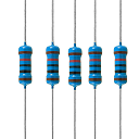
Metal film
resistors have a thin metal layer as resistive element on a non-conducting
body. They are amongst the most common types of axial resistors. Other film
type resistors are carbon film and thick and thin film resistors. In most
literature referrals to metal film, usually it is a cylindrical axial resistor.
However, thin film chip resistors use the same manufacturing principle for the
metal layer. The appearance of metal film resistors is similar to carbon film
resistors, but their properties for stability, accuracy and reliability are
considerably better.

ü Metal Oxide Film
Metal-oxide film resistors are made of ceramic rod that
is coated with a thin film of metal oxides, such as
tin oxide. Metal oxide film resistors must not be confused
with metal oxide varistors, made of zinc oxide or silicon
carbide. Metal Oxide Resistors belong to the family of fixed form
axial resistors similar to metal film resistors and carbon film resistors.
Instead of a metal film, these resistors use a metal oxide resistance material
that is coated on top of a ceramic substrate.
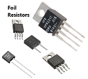
ü Foil
The metal foil resistor has the best precision and stability
properties of all resistor types. The foil is made of an alloy of usually
Nichrome with additives. It is mounted on a ceramic carrier with high heat
conductivity. The foil has a thickness of only several micrometres. The desired
resistance value is achieved by a photoetched resistive pattern in the foil.
The metal foil resistor has a low Temperature Coefficient of Resistance (TCR),
good long-term stability, low noise, low capacitance, fast thermal
stabilization and no inductance.
Depending
upon material, construction and applications, resistors are available in
different types, such as:
Ø Fixed resistors
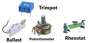
Ø Variable resistors, like:
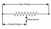
§ Potentiometer
§ Rheostat
§ Trim
pot
§ Ballast
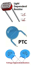
Ø Resistance dependent on a special characteristic:
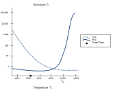
§ Thermistors (NTC and PTC) as function of temperature change
§ Photo resistor – Light Dependent Resistors (LDR) value changing as per changing
light level
§ Varistor
– Voltage Dependent Resistors (VDR) value changing as per changing voltage
§ Magneto resistor (MDR) changing
as per magnetic field
§ Strain Gauges
value changing with mechanical load
How resistors are manufactured? 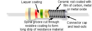
Resistors can
be constructed out of a variety of materials.
Manufacturing process and technology differs with type of material and
construction. Most common
modern resistors are made out of either a carbon, metal, or
metal-oxide film. In these resistors, a thin film of conductive (though
still resistive) material is wrapped in a helix around and covered by an
insulating material. The
process involves depositing a film of resistive material such as tin oxide
on a tiny ceramic chip. The edges of the resistor are then accurately
ground, or cut with a laser to give a precise resistance (which depends on the
width of the resistor film), across the ends of the device. Exact elaborate processes of manufacturing,
however will differ from resistor type to type.
New about resistors

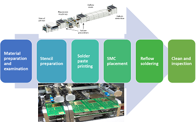
SMD (Surface Mount Devices) resistors are new in the technology
upgradation of resistors. SMT (Surface Mount Technology that uses SMD components) was
invented to both reduce the size of components and significantly reduce the
time it takes to manufacture a circuit. SMDs, are essentially very small
size resistors but without leads, are mounted on PCB surface and are connected
in circuit in wave soldering process.
SMT manufacturing is a new technology with many advantages of
manufacturing including accuracy, speed and quality.
.jpg)
CREDITS: Resistor Guide, Wikipedia, Manufacturers
websites
This is a brief overview of this topic. The subject itself is vary vast and it’s not
expected to cover every aspect here.
Technical details in this article are compiled from best known
sources. These are of course open for
any corrections and additions.